POWER PLANT ENGINEERING (UNIT-1)
UNIT – I
Introduction to the sources of energy – resources and development of power in India.
STEAM POWER PLANT: Plant layout, working of different circuits, fuel and handling equipment, types of coals, coal handling, choice of handling equipment, coal storage, ash handling systems. Combustion: properties of coal – overfeed and underfeed fuel beds, traveling grate stokers, spreader stokers, retort stokers, pulverized fuel burning system and its components, combustion needs and draught system, cyclone furnace, design and construction, dust collectors, cooling towers and heat rejection. corrosion and feed water treatment.
STEAM POWER PLANT: Plant layout, working of different circuits, fuel and handling equipment, types of coals, coal handling, choice of handling equipment, coal storage, ash handling systems. Combustion: properties of coal – overfeed and underfeed fuel beds, traveling grate stokers, spreader stokers, retort stokers, pulverized fuel burning system and its components, combustion needs and draught system, cyclone furnace, design and construction, dust collectors, cooling towers and heat rejection. corrosion and feed water treatment.
Introduction:
- The whole world is in the grip of energy crisis and the pollution manifesting itself in the spiraling cost of energy and not comforted due to increase in pollution as well as the depletion of conventional energy resources and increasing curve of pollution elements.
- To meet these challenges one way is to check growing energy demand but that would show down the economic growth as first step and to develop nonpolluting energy conversion system as second step.
- It is commonly accepted that the standard of living increases with increasing energy consumption per capita. Any consideration of energy requirement and supply has to take into account the increase conservation measures.
- On the industrial font, emphasis must be placed on the increased with constant effort to reduce energy consumption. Fundamental changes in the process, production and services can affect considerable energy saving without affecting the overall economy.
- It need not be over emphasized that in house hold commercial and industrial use of energy has considerable scope in energy saving. Attempt at understanding the integrated relationship between environment and energy have given shape due to development of R-134a, (an non pollutant refrigerant) to emerging disciplining of environmental management.
- The government of India has laid down the policy “it is imperative that we carefully utilize our renewal (i.e., non-decaying) resources of soil water, plant and animal live to sustain our economic development” our exploration or exploitation of these is reflected in soil erosion, salutation, floods and rapid destruction of our forest, floral and wild life resources.
- The depletion of these resources often tends to be irreversible since bulk of our population depends on these natural resources. Depletion of these natural resources such as fuel, fodder, and housing power plant;
Types of Energies:
There are various types of energy which, they include nuclear, electrical, thermal, chemical, and
radiant energy. In addition, gravitational potential energy and kinetic energy that combines to produce
mechanical energy.
Nuclear energy produces heat by fission on nuclei, which is generated by heat engines. Nuclear
energy is the world’s largest source of emission-free energy. There are two processes in Nuclear energy
fission and fusion. In fission, the nuclei of uranium or plutonium atoms are split with the release of
energy. In fusion, energy is released when small nuclei combine or fuse. The fission process is used in all
present nuclear power plants, because fusion cannot be controlled. Nuclear energy is used to heat steam
engines. A Nuclear power plant is a steam engine using uranium as its fuel, and it suffers from low
efficiency.
Electricity powers most factories and homes in our world. Some things like flashlights and Game
Boys use electricity that is stored in batteries as chemical energy. Other items use electricity that comes
from an electrical plug in a wall socket. Electricity is the conduction or transfer of energy from one place
to another. The electricity is the flow of energy. Atoms have electrons circling then, some being loosely
attached. When electrons move among the atoms of matter, a current of electricity is created.
Thermal energy is kinetic and potential energy, but it is associated with the random motion of
atoms in an object. The kinetic and potential energy associated with this random microscopic motion is
called thermal energy. A great amount of thermal energy (heat) is stored in the world’s oceans. Each
day, the oceans absorb enough heat from the sun to equal the energy contained in 250 billion barrels of
oil (Ocean Thermal Energy Conversion Systems).
Chemical energy is a form of energy that comes from chemical reactions, in which the chemical
reaction is a process of oxidation. Potential energy is released when a chemical reaction occurs, which is
called chemical energy. A car battery is a good example, because the chemical reaction produces
voltage and current to start the car. When a plant goes through a process of photosynthesis, what the
plant is left with more chemical energy than the water and carbon dioxide. Chemical energy is used in
science labs to make medicine and to product power from gas.
Radiant energy exists in a range of wavelengths that extends from radio waves that many be
thousands of meters long to gamma rays with wavelengths as short as a million-millionth (10– 12) of a
meter. Radiant energy is converted to chemical energy by the process of photosynthesis.
The next two types of energy go hand and hand, gravitational potential energy and kinetic
energy. The term energy is motivated by the fact that potential energy and kinetic energy are different
aspects of the same thing, mechanical energy Potential energy exists whenever an object which has mass has a position within a force field.
The potential energy of an object in this case is given by the relation
PE = mgh, where PE is energy in
joules, m is the mass of the object, g is the gravitational acceleration, and h is the height of the object goes.
Kinetic energy is the energy of motion. An object in motion, whether it be vertical or horizontal
motion, has kinetic energy.
There are different forms of kinetic energy vibrational, which is the energy
due to vibrational motion, rotational, which is the energy due to rotational motion, and transnational,
which is the energy due to motion from one location to the other. The equation for kinetic energy is ½
mv2
, where m is the mass and v is the velocity. This equation shows that the kinetic energy of an object
is directly proportional to the square of its speed.
Power Development in INDIA:
- The history of power development in India dates back to 1897 when a 200 kW hydro-station was first commissioned at Darjeeling. The first steam station was set up in Calcutta in 1899. By the end of 1920, the total capacity was 130 mW, comprising. Hydro 74 mW, thermal 50 mW and diesel 6 mW. In 1940, the total capacity goes to 1208 mW.
- There was very slow development during 1935-1945 due to Second World War. The total generation capacity was 1710 mW by the end of 1951. The development really started only after 1951 with the launching of the first five-year plan. During the First Plan, construction of a number of Major River Valley Projects like BhakraNangal, Damodar Valley, Hira Kund and Chambal Valley was taken up.
- These projects resulted in the stepping up of power generation. At the end of the First Plan, generation capacity stood at 34.2 lakh kW. Emphasis in Second Plan (1956-61) was on development of basic and heavy industries and related need to step up power generation. Installed capacity at the end of Second Plan reached 57 lakh kw. comprising 3800 mW thermal and 1900 MW hydel.
- During the Third Plan period (1961-66), emphasis was on extending power supply to rural areas. A significant development in this phase was emergence of Inter-state Grid System. The country was divided into Five Regions to promote power development on a Regional Basis. A Regional Electricity Board was established in each region to promote integrated operation of constituent power system.
- Three Annual Plans that followed Third Plan aimed at consolidating programmes initiated during the Third Plan. Fourth Plan envisaged need for central participation in expansion of power generation programmes at strategic locations to supplement activities in the State Sector. Progress during the period covering Third Plan, three Annual Plans and Fourth Plan was substantial with installed capacity rising to 313.07 lakh kW compression; 113.86 lakh kW from Hydro-electric Projects, 192.81 lakh kW from Thermal Power Projects and balance of 6.4 lakh kW from Nuclear Projects at the end of the Fifth Plan. During the Sixth Plan, total capacity addition of 196.66 lakh kW comprising Hydro 47.68 lakh kW, Thermal 142.08 lakh kW and Nuclear 6.90 lakh kW was planned. Achievement, however, has been 142.26 lakh kW (28.73 lakh kW Hydro, 108.98 lakh kW Thermal and 4.55 lakh kW Nuclear) 72.3 per cent of the target.
- The Seventh Plan power programme envisaged aggregate generating capacity of 22,245 mW in utilities. This comprised 15,999 mW Thermal, 5,541 mW Hydro and 705 mW Nuclear of the anticipated 22,245 mW additional capacity. Central Sector Programme envisaged capacity addition of 9,320 mW (7,950 mW Thermal, 665 mW Hydro and 705 mW Nuclear) during the Plan Period. During the Seventh Plan, 21401.48 mW has been added comprising 17104.1 mW Thermal 3,827.38 mW Hydro and 470 mW Nuclear. Year wise commissioning of Hydro, Thermal and Nuclear Capacity added during 1985-86 to 1989-90 is given in.The Working Group on Power set up particularly the Planning Commission in the context of formulation of power programme for the Eighth Plan has recommended a capacity addition programme of 38,369 mW for the Eighth Plan period, out of which it is expected that the Central Sector Projects would add a capacity of 17,402 mW.
- The programme for the first year of the Eighth Plan (1990-91) envisages generation of additional capacity of 4,371.5 mW comprising 1,022 mW Hydro, 3,114.5 mW Thermal and 235 mW Nuclear. The subject ‘Power’ appears in the Concurrent List of the Constitution and as such responsibility of its development lies both with Central and state governments. At the Centre, Department of Power under the Ministry of Energy is responsible for development of Electric Energy.
- The department is concerned with policy formulation, perspective planning, procuring of projects for investment decisions, monitoring of projects, training and manpower development, administration and enactment of Legislation in regard to power generation, transmission and distribution. The depart-ment is also responsible for administration of the Electricity (Supply) Act, 1948 and the Indian Electricity Act, 191() and undertakes all amendments thereto. The Electricity (Supply) Act, 1948, forms basis of administrative structure of electricity industry. The Act provides for setting up of a Central Electricity Authority (CEA) with responsibility, inter-alia, to develop a National Power Policy and coordinate activities of various agencies and State Electricity Boards. The act was amended in 1976 to enlarge scope and function of CEA and enable of creation of companies for generation of electricity. The Central Electricity Authority advises Department of Power on technical, financial and economic matters. Construction and operation of generation and transmission projects in the Central Sector are entrusted to Central Power Corporations, namely, National Thermal Power Corpora-tion (NTPC), National Hydro-Electric Power Corporation (NHPC) and North-Eastern Electric Power Corporation (NEEPCU) under administrative control of the Department of Power. The Damodar Valley Corporation (DVC} constituted under the DVC Act, 1948 and the Bhitkra Beas, Management Board (BBMB) constituted under the Punjab Reorganization. Act, 1966, is also under administrative control of the Department of Power. In addition, the department administers Beas Construction Board (BCB) and National Projects Construction Corporation (NPCC), which are construction agencies and training and research organisations, Central Power Research Institute (CPRI) and Power Engineers Training Society (PETS). Programs of rural electrification are within the purview of Rural Electrification Corporation (REC) which is a financing agency. ‘‘There are two joint venture Power Corporations under the administrative control of the Department of Power, namely, Nathpa jhakri Power Corporation and Tehri Hydro Development Corporation which are responsible for the execution of the Nathpa Jhakri Power Project and Projects of the Tehri Hydro Power Complex respectively. In addition to this, Energy Manage-ment Centre, an autonomous body, was established in collaboration with the European Economic Community, which is responsible for training, research, and information exchange between energy professionals. It is also responsible for conservation of energy programmes/activities in the Department of Power. Significant progress has been made in the expansion of transmission and distribution facilities in the Country. Total length of transmission lines of 66 kV and above increased from 10,000 ckt (circuit) km in December 1950 to 2.02 lakh ckt Km in March, 1990. Highest transmission voltage in the Country at present is 400 kV and above 19800 ckt km of 400 kV lines had been constructed up to March, 1990 and about 18000 ckt km of these are in actual operation. Prior to the Fourth Plan, Transmission Systems in the Country were developed more or less as state systems, as generating stations were built primarily in the State Sector. When State Transmission Systems had developed to a reasonable extent in the Third Plan, potentiality of inter-connected operation of individual state systems with other neighboring systems within the region (northern, western, southern, eastern and north-eastern) was thought of. Fairly well inter-connected systems at voltage of 220 kV with progressive overlay of 400 kV are presently available in all regions of the Country except North-eastern Region. With creation of Two Generation Corporations, namely National Thermal Power Corporation and National Hydro-Electric Power Corporation in 1975, the Centre had started playing an increasingly larger role in the development of grid systems. The 400 kV transmission systems being constructed by these organizations as part of their generation projects, along with 400 kV inter-state and inter-regional transmission lines would form part of the National Power Grid. National Power Grid will promote integrated operation and transfer of power from one system to another with ultimate objective of ensuring optimum utilization of resources in the Country. India now has well integrated Regional Power Systems and exchange of power is taking place regularly between a large numbers of state systems, which greatly facilitates better utilization of existing capacity
Steam Power Plant:
Steam is an important medium of producing mechanical energy. Steam has the advantage that, it
can be raised from water which is available in abundance it does not react much with the materials of the
equipment of power plant and is stable at the temperature required in the plant. Steam is used to drive
steam engines, steam turbines etc. Steam power station is most suitable where coal is available in abundance.
Thermal electrical power generation is one of the major method. Out of total power developed in
India about 60% is thermal. For a thermal power plant the range of pressure may vary from 10 kg/cm2
to
super critical pressures and the range of temperature may be from 250°C to 650°C.

Essentials of Steam Power Plant Equipment:
A steam power plant must have following equipment :
(a) A furnace to burn the fuel.
(b) Steam generator or boiler containing water. Heat generated in the furnace is utilized to convert water into steam.
(c) Main power unit such as an engine or turbine to use the heat energy of steam and perform work. (d) Piping system to convey steam and water.
In addition to the above equipment the plant requires various auxiliaries and accessories depending upon the availability of water, fuel and the service for which the plant is intended.
The flow sheet of a thermal power plant consists of the following four main circuits :
(a) Feed water and steam flow circuit.
(b) Coal and ash circuit.
(c) Air and gas circuit.
(d) Cooling water circuit.
A steam power plant using steam as working substance works basically on Rankine cycle. Steam is generated in a boiler, expanded in the prime mover and condensed in the condenser and fed into the boiler again. The different types of systems and components used in steam power plant are as follows
(a) High pressure boiler
(b) Prime mover
(c) Condensers and cooling towers
(d) Coal handling system
(e) Ash and dust handling system
(f) Draught system
(g) Feed water purification plant
(h) Pumping system
(i) Air preheater, economizer, super heater, feed heaters.
Figure shows a schematic arrangement of equipment of a steam power station. Coal received in coal storage yard of power station is transferred in the furnace by coal handling unit. Heat produced due to burning of coal is utilized in converting water contained in boiler drum into steam at suitable pressure and temperature. The steam generated is passed through the superheater. Superheated steam then flows through the turbine. After doing work in the turbine the pressure of steam is reduced. Steam leaving the turbine passes through the condenser which is maintained the low pressure of steam at the exhaust of turbine. Steam pressure in the condenser depends upon flow rate and temperature of cooling water and on effectiveness of air removal equipment. Water circulating through the condenser may be taken from the various sources such as river, lake or sea. If sufficient quantity of water is not available the hot water coming out of the condenser may be cooled in cooling towers and circulated again through the condenser. Bled steam taken from the turbine at suitable extraction points is sent to low pressure and high pressure water heaters.
Air taken from the atmosphere is first passed through the air pre-heater, where it is heated by flue gases. The hot air then passes through the furnace. The flue gases after passing over boiler and superheater tubes, flow through the dust collector and then through economiser, air pre-heater and finally they are exhausted to the atmosphere through the chimney. Steam condensing system consists of the following :
(a) Condenser
(b) Cooling water
(c) Cooling tower
(d) Hot well
(e) Condenser cooling water pump
(f) Condensate air extraction pump
(g) Air extraction pump
(h) Boiler feed pump
(i) Make up water pump.
Power Station Design:
Power station design requires wide experience. A satisfactory design consists of the following
steps :
(i) Selection of site
(ii) Estimation of capacity of power station.
(iii) Selection of turbines and their auxiliaries.
(iv) Selection of boilers, and their auxiliaries.
(v) Design of fuel handling system.
(vi) Selection of condensers.
(vii) Design of cooling system.
(viii) Design of piping system to carry steam and water.
(ix) Selection of electrical generator.
(x) Design and control of instruments.
(xi) Design of layout of power station. Quality of coal used in steam power station plays an
important role in the design of power plant. The various factors to be considered while
designing the boilers and coal handling units are as follows :
(a) Slagging and erosion properties of ash.
(b) Moisture in the coal. Excessive moisture creates additional problems particularly in case
of pulverized fuel power plants.
(c) Burning characteristic of coal.
(d) Corrosive nature of ash.
FUEL HANDLING:
Three types of fuels can be burnt in any type of steam generating plant:
1. Solid fuel such as coal
2. Liquid fuel as oil and
3. Gaseous fuel as gas.
Supply of these fuels to the power plants from various sources is one of the important considerations for a power plant engineer. The handling of these fuels is an important aspect. The following factors should be considered in selecting the fuel handling system :
1.Plant fuel rate.
2.Plant location in respect of fuel shipping.
3.Storage area available.
Fuel handling plant needs extra attention, while designing a thermal power station, as almost 50 to 60 percent of the total operating cost consists of fuel purchasing and handling. Fuel system is designed in accordance with the type and nature of fuel. Continuously increasing demand for power at lower cost calls for setting up of higher capacity power stations. Rise in capacity of the plant poses a problem in coal supply system from coal mines to the power stations. The coal from coal mines may be transported by the following means:
1. Transportation by sea or river,
2. Transportation by rail,
3. Transportation by rope ways,
4. Transportation by road,
5. Transportation of coal by pipeline.
The pipeline coal transport system offers the following advantages:
1.It provides simplicity in installation and increased safety in operation.
2. More economical than other modes of transport when dealing with large volume of coal over long distances.
3. This system is continuous as it remains unaffected by the vagaries of climate and weather.
4. High degree of reliability.
5. Loss of coal during transport due to theft and pilferage is totally eliminated.
6. Manpower requirement is low.
Requirements of Good Coal Handling Plant:
1. It should need minimum maintenance.
2. It should be reliable.
3. It should be simple and sound.
4. It should require a minimum of operatives.
5. It should be able to deliver requisite quantity of coal at the destination during peak periods.
6. There should be minimum wear in running the equipment due to abrasive action of coal particles.
Coal Handling Systems:
"Mechanical handling" of coal is preferred over "manual handling" due to the following reasons :
1. Higher reliability.
2. Less labour required.
3. Economical for medium and large capacity plants.
4. Operation is easy and smooth.
5. Can be easily started and can be economically adjusted according to the need.
6. With reduced labour , management and control of the plant becomes easy and smooth.
7. Minimum labour is put to unhealty condition.
8. Losses in transport are minimised.
Disadvantages:
1. Needs continuous maintenance and repair.
2. Capital cost of the plant is increased.
3. In mechanical handling some power generated is usually consumed, resulting in less net power available for supply to consumers.


Coal Transfer
The following equipment may be used for transfer of coal:
1.Belt conveyors
2.Screw conveyors
3.Bucket elevator and conveyor
4.Pivoted bucket conveyor
5.Grab bucket conveyor
6.Flight conveyors (or scrapers)
7.Skip hoists
8.Mass flow conveyor
9.Chutes.
BELT CONVEYOR:
It consists of an endless belt, moving over a pair of end drums (rollers). The belt is made, up of rubber or canvas. Belt conveyor is suitable for the transfer of coal over long distances. It is used in medium and large power plants. The initial cost of the system is not high and power consumption is also low. The inclination at which coal can be successfully elevated by belt conveyor is about 20°. Average speed of belt conveyors varies between 200-300 R.P.M.

Advantages of belt conveyor
1. Its operation is smooth and clean.
2. It requires less power as compared compared to other types of systems .
3. Large quantities of coal can be discharged quickly and continuously.
4. Material can be transported on moderates inclines.
SCREW CONVEYOR:
It consists of an endless helicoids screw fitted to a shaft. The screw while rotating in a trough transfers the coal from feeding end to the discharge end. This system is suitable, where coal is to be transferred over shorter distance and space limitations exist. The initial cost of the system is low. It suffers from the drawbacks that the power consumption is high and there is considerable wear of screw. Rotation of screw varies between 75-125 R.P.M.


Carbon: The elements carbon expressed on dry mineral matter free (DMMF-Dry Mineral Matter Free Basis) basis should vary between 85-88%. ·
FUEL HANDLING:
Three types of fuels can be burnt in any type of steam generating plant:
1. Solid fuel such as coal
2. Liquid fuel as oil and
3. Gaseous fuel as gas.
Supply of these fuels to the power plants from various sources is one of the important considerations for a power plant engineer. The handling of these fuels is an important aspect. The following factors should be considered in selecting the fuel handling system :
1.Plant fuel rate.
2.Plant location in respect of fuel shipping.
3.Storage area available.
Fuel handling plant needs extra attention, while designing a thermal power station, as almost 50 to 60 percent of the total operating cost consists of fuel purchasing and handling. Fuel system is designed in accordance with the type and nature of fuel. Continuously increasing demand for power at lower cost calls for setting up of higher capacity power stations. Rise in capacity of the plant poses a problem in coal supply system from coal mines to the power stations. The coal from coal mines may be transported by the following means:
1. Transportation by sea or river,
2. Transportation by rail,
3. Transportation by rope ways,
4. Transportation by road,
5. Transportation of coal by pipeline.
The pipeline coal transport system offers the following advantages:
1.It provides simplicity in installation and increased safety in operation.
2. More economical than other modes of transport when dealing with large volume of coal over long distances.
3. This system is continuous as it remains unaffected by the vagaries of climate and weather.
4. High degree of reliability.
5. Loss of coal during transport due to theft and pilferage is totally eliminated.
6. Manpower requirement is low.
Requirements of Good Coal Handling Plant:
1. It should need minimum maintenance.
2. It should be reliable.
3. It should be simple and sound.
4. It should require a minimum of operatives.
5. It should be able to deliver requisite quantity of coal at the destination during peak periods.
6. There should be minimum wear in running the equipment due to abrasive action of coal particles.
Types of Coals:
There are four major types (or “ranks”) of coal. Rank refers to steps in a slow, natural process called “coalification,” during which buried plant matter changes into an ever denser, drier, more carbon rich, and harder material. The four ranks are:
- Anthracite: The highest rank of coal. It is a hard, brittle, and black lustrous coal, often referred to as hard coal, containing a high percentage of fixed carbon and a low percentage of volatile matter.
- Bituminous: Bituminous coal is a middle rank coal between sub bituminous and anthracite. Bituminous usually has a high heating (Btu) value and is the most common type of coal used in electricity generation in the United States. Bituminous coal appears shiny and smooth when you first see it, but look closer and you may see it has layers.
- Sub bituminous: Sub bituminous coal is black in color and dull (not shiny), and has a higher heating value than lignite.
- Lignite: Lignite coal, aka brown coal, is the lowest grade coal with the least concentration of carbon.
Also, there is peat. Peat is not actually coal, but rather the precursor to coal. Peat is a soft organic material consisting of partly decayed plant and, in some cases, deposited mineral matter. When peat is placed under high pressure and heat, it becomes coal.
Coal Handling Systems:
"Mechanical handling" of coal is preferred over "manual handling" due to the following reasons :
1. Higher reliability.
2. Less labour required.
3. Economical for medium and large capacity plants.
4. Operation is easy and smooth.
5. Can be easily started and can be economically adjusted according to the need.
6. With reduced labour , management and control of the plant becomes easy and smooth.
7. Minimum labour is put to unhealty condition.
8. Losses in transport are minimised.
Disadvantages:
1. Needs continuous maintenance and repair.
2. Capital cost of the plant is increased.
3. In mechanical handling some power generated is usually consumed, resulting in less net power available for supply to consumers.

Coal Delivery :
- The coal from supply points is delivered by ships or boats to PP if near to sea or river
- Rail or trucks to the power stations which are situated away from sea or river.
- Trucks is used if railway facilities are not available.
Unloading:
- The type of equipment to be used for unloading the coal received at power station depends on how coal is received received at the power station station.
- If coal is delivered by trucks, there is no need of unloading device as the trucks may dump the coal to the outdoor storage.
- In case the coal is brought by railway wagons, ships or boats, the unloading may be done by car shakes, rotary car dumpers, cranes, grab buckets and coal accelerators. Rotary car dumpers although costly, are quite efficient for unloading closed wagons.
Preparation:
- When the coal delivered is in the form of big lumps and it is not of proper sire, the preparation (sizing) of coal can be achieved by crushers, breakers, sizer driers and magnetic separators.

- 'Transfer' means the handling of coal between the unloading point and the final storage point from here it is discharged to the firing equipment.
The following equipment may be used for transfer of coal:
1.Belt conveyors
2.Screw conveyors
3.Bucket elevator and conveyor
4.Pivoted bucket conveyor
5.Grab bucket conveyor
6.Flight conveyors (or scrapers)
7.Skip hoists
8.Mass flow conveyor
9.Chutes.
BELT CONVEYOR:
It consists of an endless belt, moving over a pair of end drums (rollers). The belt is made, up of rubber or canvas. Belt conveyor is suitable for the transfer of coal over long distances. It is used in medium and large power plants. The initial cost of the system is not high and power consumption is also low. The inclination at which coal can be successfully elevated by belt conveyor is about 20°. Average speed of belt conveyors varies between 200-300 R.P.M.

Advantages of belt conveyor
1. Its operation is smooth and clean.
2. It requires less power as compared compared to other types of systems .
3. Large quantities of coal can be discharged quickly and continuously.
4. Material can be transported on moderates inclines.
SCREW CONVEYOR:
It consists of an endless helicoids screw fitted to a shaft. The screw while rotating in a trough transfers the coal from feeding end to the discharge end. This system is suitable, where coal is to be transferred over shorter distance and space limitations exist. The initial cost of the system is low. It suffers from the drawbacks that the power consumption is high and there is considerable wear of screw. Rotation of screw varies between 75-125 R.P.M.

BUCKET ELEVATOR:
It consists of buckets fixed to a
chain. The chain moves over two
wheels. The coal is carried by the
buckets from bottom and discharged at
the top.

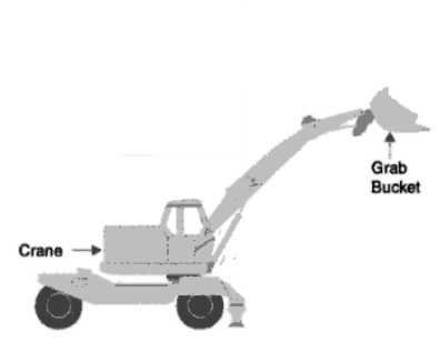
GRAB BUCKET ELEVATOR:
It lifts and transfers coal on a single rail or track from one point
to the other. The coal lifted by grab buckets is transferred to overhead
bunker or storage.
This system requires less power for operation and requires
minimum maintenance.
The grab bucket conveyor can be used with crane or tower as
shown in Fig. Although the initial cost of this system is high but
operating cost is less.

SKIP HOISTS
It consists of a vertical or inclined
hoist way. A bucket or a car guided
by a frame and a cable for hoisting
the bucket.
The bucket is held in up right
position. It is simple and compact
method of elevating elevating coal or ash.

FLIGHT CONVEYOR:
It consists of one or two strands of
chain to which steel scraper or flights are
attached, which scrap the coal through a
depression having identical shape.
It is used to drag or push pulverized
or granulated solid materials. This coal is
discharged in the bottom of trough.
It is low in first cost but has large
energy consumption. There is considerable
wear.
It may be used for coal as well as
ash.

COAL STORAGE:
Why storage ??
It gives protection against the interruption/ delay of coal
supplies.
Also when the prices are low, the coal can be purchased and
stored for future use.
How much ??
The amount of coal to be stored depends on the availability of
space for storage, transportation facilities, transportation facilities, the amount of coal that will
whether away and nearness to coal mines of the power station.Usually coal required for one month operation of power plant
is stored in case of power stations situated at longer distance from the
collieries whereas coal need for about 15 days is stored in case of
power station situated near to collieries.
Any disadvantage??
Storage of coal for longer periods is not advantageous because
it blocks the capital and results in deterioration of the quality of coal.
Dead storage or Outdoor storage:
The coal stored has the tendency to whether (to combine with
oxygen of air). Due to low oxidation the coal may ignite
spontaneously. This is avoided by storing coal in the form of piles
so that air cannot pass through the coal piles.
The coal is stored by the following methods:
- Stocking the coal in heats. The coal is piled on the ground up to 10-12 m height. The pile top should be given a slope in the direction in which the rain may be drained off. The sealing of stored pile is desirable in order to avoid the oxidation of coal after packing an air tight layer of coal. Asphalt, fine coal dust and bituminous coating are the materials commonly used for this purpose.
- Under water storage. The possibility of slow oxidation and spontaneous combustion can be completely eliminated by storing the coal under water
- Live coal storage implies the reclaiming and combustion of coal that has been stored for only a relatively short time, usually less than a week.
- Coal from a live coal (storage pile is usually supplied to combustion equipment without the use of mobile equipment.
- The coal is usually stored in the vertical cylinder bunkers or coal bins or silo. Coal from silos is transferred to the boiler grate.
In plant handling:
It is referred to transferring coal from dead or live storage to the boiler
furnace. For in plant handling, the same equipment are used as used for
coal transfer like belt conveyors, screw conveyors, bucket elevators etc.

Coal Weighting:
The commonly used methods to weigh the coal
are as follows:
(i) Mechanical (ii) Pneumatic (iii) Electronic.
- The Mechanical method works on a suitable lever system - mounted on knife edges and bearings - connected to a resistance in the form of a spring of pendulum.
- The Pneumatic weighters use a pneumatic transmitter weight head - the corresponding air pressure determined by the load applied.
- The Electronic weighing machines make use of load cells that produce voltage signals proportional to the load applied.
Dewatering of Coal:
Excessive surface moisture of coal reduces heating
value of coal and creates handling problems. The coal
should therefore be dewatered to produce clean coal.
Cleaning of coal has the following advantages:
- Improved heating value.
- Easier crushing and pulverizing
- Easy handling and transportation
- Improve boiler performance
- Reduce amount of ash handling
Properties of Coal:
Various properties of coals which gives rise to the manufacture of coke
A) Chemical properties: ·
A) Chemical properties: ·
Carbon: The elements carbon expressed on dry mineral matter free (DMMF-Dry Mineral Matter Free Basis) basis should vary between 85-88%. ·
Hydrogen: The hydrogen DMMF basis should vary between 3.7 to 4.5%.
Sulpher: In the suplher both organic & inorganic should not exceed 0.75%
on DMMF basis.
Phosphorous: The Phosphorous present in the coking coal should not exceed
0.15 – 0.25%.
·
Other elements: Such as Nitrogen, Iron & Other rarer elements must be
present in traces.
B) Mineral Matter:
The mineral matter in the coking coal normally should not exceed 20% under any
circumstances since the mineral matter constitute a portion of inert matter hence its
quality should not exceeds 20%. There are 2 kinds of MM in the coal. (i) Inherent
MM and (ii) Extraneous.
It has not yet been possible to reduces the extraneous MM,
that too, up to a certain extent.
C) Physical Properties:
The development of coking property is an intrinsic property. The reason for
development of coking property has not yet been clearly established. By physical
tests it can be determined whether the coal is coking or non-coking. The following
destructive physical test is used for finding the coking propensity of coal.
1. Geisler Plastometer:
Equipment should give a reading between 500 to
2000 dial divisions per minute. Higher the fluidity of coal mass, batter will be
the dials division per minute.
2. Caking Index:
In this test certain amount of powered coal is thoroughly
mixed with graded and sized sand. The total quantity of sand and coal should
not exceed 25 grams. This mixture when heated at 9250 in the absence of
air, after cooling down should a coherent residue. This coherent residue
should be able to withstand a weight of 500 grams without generating more
than 5% of powder out of the residue. If the solid residue more than 5% then
the proportion of coal in the mixture of sand and coal should be increased and
vice versa. Normally caking index for coking coal should vary from 20-24 for
bee-hive oven the minimum index should be 13 and maximum 24.
3. Swelling Index:
During determination of volatile matter in coking coal a
solid reside in left, comprising of fixed carbon and mineral matter. The solid
residue that is the coke bead is viewed horizontally at the same level of the
eye. It will be observed that the top surface of the bead has developed some
amount of swelling. This swelling is compared with standard chart indicating
there quantum of swelling and a number indicating swelling index. Swelling
index varying between 2.-5 is ideal for coke manufacturing. The high swelling
coal is not charged for coke making as it would create unnecessary pressure
on the side wall of the oven will also produce a coke porous structure.
4. Volatile Matter:
The volatile matter of coking coal should vary between 19-
26% on DMMF basis. A coal with less VM then 19% will give rise to a coke
which will not have proper physical property. A coal with VM higher than 26%
will give rise to coke with more porosity and physical strength, such as CSR
and CRI. The VM in coal consist of various gaseous products which has
generated when the coal is heated in absence of air at temperature more than
900o C. The gases, consists of combination of carbon and hydro-aromatic
compound. The gases mainly methane, Acetylene, gaseous Amino –
compound. The gases mainly Mathane, Hydrogen and Carbon and some other
hydrogen-aromatic compounds such as phenol and benzene. Some amount of
tar in gaseous from is also generated.
5. Petrographic Analysis and Reflectance:
Another most important nondestructive
test of coal which is used for determining of coking coal is the
petrographic analysis & reflectance. The coking coal should have a minimum
of 60% virtrain (active constituents) and maximum of 40% Inertinite (nonreactive
constituent). For finding out the physical strength of the coke,
reflectance studies on coking coal are also done. In this study the ideal value
of reflectance will be within 1.3 – 1.5. Generally the coking property develops
in coal if it reflectance is between 0.9 – 1.3.
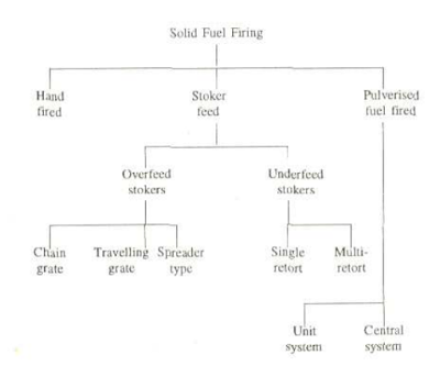
Fuel Firing:
Fuel is burnt in a confined space called furnace. In the furnace: Burners are used to burn powdered (Pulverized) coal and liquid or gaseous fuels ; Grate with stoker require for solid fuels.
How to select proper type and size of furnace..??
It depends upon the following factors:

Fuel Firing:
Fuel is burnt in a confined space called furnace. In the furnace: Burners are used to burn powdered (Pulverized) coal and liquid or gaseous fuels ; Grate with stoker require for solid fuels.
How to select proper type and size of furnace..??
It depends upon the following factors:
- Type of fuel to be burnt.
- Type of firing to be used.
- Amount of heat to be recovered.
- Amount of steam to be produced
- Pressure and temperature desired.
- Grate area required.
- Ash fusion temperature.
- Flame length.
- Amount of excess air to be used.
TYPES OF FURNACES
1. Grate fired furnaces: They are used to burn solid fuels.They
may have a stationary or a movable bed of fuel.These furnaces are classified as under depending upon the method
used to fire the fuel and remove ash and slag.
A. Hand fired and Semi-mechanized
B. Stocker fired.
Hand fired and semi-mechanized furnaces are designed
with stationary fire grates and stoker furnaces with traveling
grates or stokers.
2. Chamber fired furnaces: They are used to burn pulverized
fuel, liquid and gaseous fuels.

What may be the material of furnace ?
Simply furnace walls consists of an interior face of refractory material such as
fire clay, silica, alumina and kaolin,
an intermediate layer of insulating materials
such as magnesia with
the exterior casing made up of steel sheet.
Smaller boilers used solid refractory
walls but they are air cooled. In larger units,
bigger boilers use water cooled furnaces.
HAND FIRING
- This is a simple method - less capital investment and used for smaller plants. This method of fuel firing is discontinuous process, and there is a limit to the size of furnace which can be efficiently fired by this method.
- While burning coal the total area of air openings varies from 30 to 50% of the total grate area.
- Hand fired grates are made up of cast iron.

- Fig. shows a hand fire grate furnace with a stationary fuel bed.
- The grate divides it into the furnace space in which - the fuel is fired and - an ash pit through which the necessary air required for combustion is supplied.
- The grate is arranged horizontally and supports a stationary bed of burning fuel.
- The fuel is charged by hand through the fire door.
- In a hand fired furnace the bed is periodically shoveled on to grate, and is heated up by the burning fuel and hot masonry of the furnace.
The heal liberation per unit of furnace volume
is given by the following expression:
h = (W X C) X V where
H = Heat liberation per unit volume
W = Rate of fuel consumption (kg/sec)
C = Lower heating value of fuel (kcal/kg)
V = Volume of furnace (m
3)
MECHANICAL FIRING (STOKERS)
Mechanical stokers are commonly used to feed solid fuels into the furnace in medium and large size power plants.The various advantages of stoker firing are as follows :
- Large quantities of fuel can be fed into the furnace. Thus greater combustion capacity is achieved
- Poorer grades of fuel can be burnt easily.
- Stoker save labour of handling ash and are self-cleaning.
- By using stokers better furnace conditions can be maintained by feeding coal at a uniform rate.
- Stokers save coal and increase the efficiency of coal firing.
The main disadvantages of stokers are
- Their more costs of operation and repairing resulting from high furnace temperatures.
The working of various types of stokers is based on the following two principles:
1. Overfeed Principle
2. Under feed Principle
The selection of firing method adopted for a particular power
plant depends upon the following factors :
(1)The characteristics of the available coal.
(2)Capacity of the plant.
(3)Load factor of the power plant.
(4)Nature of load fluctuation
(5)Reliability and efficiency of the various combustion
equipment available.
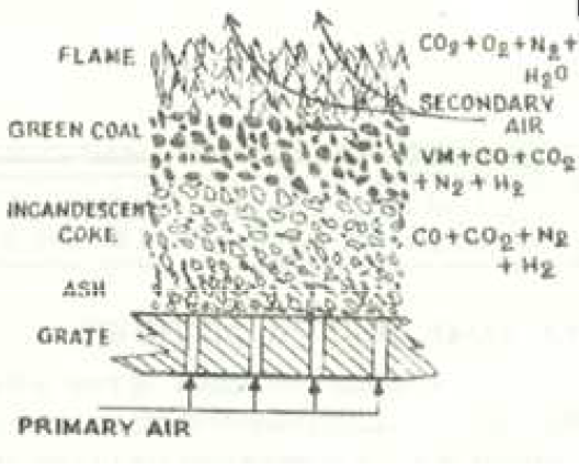
Overfeed supply of coal:
In case of overfeed stoker, coal is fed on to the grate above the
point of air admission as shown in Fig.

The mechanics of combustion in overfeed stoker is described below :
(1) The pressurized air coming from F.D. fan enters under the bottom of the grate. The air passing through the grate is heated by absorbing the heat from the ash and grate itself, whereas the ash and grate are cooled. The hot air then passes through a bed of incandescent coke. As the hot air passes through incandescent coke, the O2 reacts with C to form C02. Generally, for a fuel bed of 8 cm deep, all the O2 in the air disappears in the incandescent region. The gases leaving the incandescent region of fuel bed consist of N2, CO2, CO, H2 and H2O.
(2) The raw coal is continuously supplied on the surface of the bed. Here it loses its volatile matter by distillation.
(3) The gases leaving the upper surface of the fuel bed contain combustible volatile matter formed from the raw fuel, N2, CO2, CO, H2 and H2O. Additional secondary air is supplied at top of the bed to burn the remaining combustible gases (volatile matter + CO + H2). The secondary air is supplied at a very high speed to create turbulence which is required for complete combustion of unburned gases.
(4) The burned gases entering boiler contain N2, CO2, 02 and H20 and some
CO if the burning is incomplete.
Under-feed supply of coal: In this type of stokers, the fuel and air move in the same direction.

The mechanism of combustion in under-feed stoker is described below :
(1) Air after passing through the holes in the grate as shown in Fig. meets the raw coal. The heat for distillation comes by conduction from the mass of incandescent fuel bed which exists above the raw
coal. The air mixes with the formed volatile matter and passes through the ignition zone and then enters into the region of incandescent coke.
(2) The reactions which take place in the incandescent zone of underfeed stoker are very much similar as in the feed incandescent zone of overfeed stoker.
(3) The gases coming out of raw fuel bed pass through a region of incandescent ash on surface of the fuel and finally discharged to the furnace with the constituents like over-feed stoker
(4) The supply of secondary air is required in this case as the gases coming out of fuel bed also contain combustible matter.
Under feed Vs Over feed:
OVER FEED STOKER
These types of stokers are used for large capacity boiler installations where the coal is burned without pulverization. The overfeed stokers are of mainly two types
(a) Traveling grate stoker
(b) Spreader stoker.
Travelling Stoker:
The travelling stoker may be chain grate type or bar grate type. These two differ only in the details of grate construction.


Overfeed supply of coal:
In case of overfeed stoker, coal is fed on to the grate above the
point of air admission as shown in Fig.
The mechanics of combustion in overfeed stoker is described below :
(1) The pressurized air coming from F.D. fan enters under the bottom of the grate. The air passing through the grate is heated by absorbing the heat from the ash and grate itself, whereas the ash and grate are cooled. The hot air then passes through a bed of incandescent coke. As the hot air passes through incandescent coke, the O2 reacts with C to form C02. Generally, for a fuel bed of 8 cm deep, all the O2 in the air disappears in the incandescent region. The gases leaving the incandescent region of fuel bed consist of N2, CO2, CO, H2 and H2O.
(2) The raw coal is continuously supplied on the surface of the bed. Here it loses its volatile matter by distillation.
(3) The gases leaving the upper surface of the fuel bed contain combustible volatile matter formed from the raw fuel, N2, CO2, CO, H2 and H2O. Additional secondary air is supplied at top of the bed to burn the remaining combustible gases (volatile matter + CO + H2). The secondary air is supplied at a very high speed to create turbulence which is required for complete combustion of unburned gases.
(4) The burned gases entering boiler contain N2, CO2, 02 and H20 and some
CO if the burning is incomplete.
Under-feed supply of coal: In this type of stokers, the fuel and air move in the same direction.

(1) Air after passing through the holes in the grate as shown in Fig. meets the raw coal. The heat for distillation comes by conduction from the mass of incandescent fuel bed which exists above the raw
coal. The air mixes with the formed volatile matter and passes through the ignition zone and then enters into the region of incandescent coke.
(2) The reactions which take place in the incandescent zone of underfeed stoker are very much similar as in the feed incandescent zone of overfeed stoker.
(3) The gases coming out of raw fuel bed pass through a region of incandescent ash on surface of the fuel and finally discharged to the furnace with the constituents like over-feed stoker
(4) The supply of secondary air is required in this case as the gases coming out of fuel bed also contain combustible matter.
Under feed Vs Over feed:
- The under-feed method of fuel supply is best for semi-bituminous and bituminous coals high in volatile matter.
- The volatile matter gets heated to a high temperature as it passes through incandescent region of coal. The volatile matter being at a higher temperature before entering the furnace burns quickly when mixed with secondary air.
- In case of over-feed burning, the volatile matter will be somewhat cooler than the furnace gases and therefore it requires longer time for complete burning. This may create a tendency to form smoke.
OVER FEED STOKER
These types of stokers are used for large capacity boiler installations where the coal is burned without pulverization. The overfeed stokers are of mainly two types
(a) Traveling grate stoker
(b) Spreader stoker.
Travelling Stoker:
The travelling stoker may be chain grate type or bar grate type. These two differ only in the details of grate construction.
- The grate surface of a chain grate stoker is made of a series of cast iron links connected by pins to form an endless chain.
- The grate surface of a bar grate stoker is made of a series of cast iron sections mounted on carrier bars. The carrier bar rides on two endless type drive chains.

The air required for combustion is supplied through the air inlets situated below the grate. The secondary air is supplied through the openings provided in the furnace wall above the grate as shown in figure.
The advantages of chain grate stoker are listed below :
- It is simple in construction and its initial cost is low.
- It is more reliable in service therefore maintenance charges are low.
- It is self-cleaning stoker.
- The heat release rates can be controlled just by controlling the speed of chain.
- It gives high heat release rates per unit volume of the furnace.
Disadvantages:
- The amount of coal carried on the grate is small as the increase in grate size creates additional problems. This cannot be used for high capacity boilers 200 tons/hr or more.
- The temperature of preheated air is limited to 180°C.
- The clinker troubles are very common.
- There is always some loss of coal in the form of fine particles carried with the ashes.
These grates are suitable only when fuel burns before it reaches the rear end of the furnace. The rate of burning with this stoker is 200 to 300 kg per m² per hour when forced draught is used.
- Another type of travelling stoker is vibrating grate stoker. It operates in a manner similar to that of chain grate stoker except that the fuel bed movement are accomplished by vibration. The vibration and the inclination of the grate cause the fuel bed to move through furnace towards ash pit.
- Chain grate stokers are best suited for non-caking, high volatile and high ash coals.
- The bar grate stokers burn lignite and small size anthracite coals successfully.
- Vibrating grate stokers are suitable for medium volatile bituminous coals and lignites but at reduced burning rates. The travelling stokers are not suitable for caking coal at it requires agitation during burning.
This is a overfeed type stoker. The coal burns on this stoker remains partly in suspension and partly on the grate.

The spreader stoker installation consists of variable feeding device, a mechanism for throwing the coal uniformly on the grate and with suitable openings for admitting the air. Air supplied by F.D. fan enters the furnace through the openings provided in the grate. A portion of this air is used to burn the fuel on the bed and remaining air is used to burn volatile matter in suspension. Secondary supply of air creates high turbulence and complete the combustion of volatile matter and suspended particles.
The advantages of spreader stoker are:
- A wide variety of coal from lignite to semi anthracite as well as high ash coal can be burn easily.
- Clinkering difficulty is reduced by spreading action.
- The coking tendency of the coal is reduced before it reaches the grate by the release of volatile gases which burn in suspension.
- The use of high temperature preheated air is possible.
- It gives quick response to load change similar to pulverized fuel system because there is only a small amount of fuel on the grate at any time and most of heat is released during burning of the coal in suspension.
- This form of fixing provides thin and even fire bed and results in high rate of combustion (350 kg/m²-hr). Therefore, it gives quick response to the load change and with less sensitivity to the swelling characteristics of the fuel.
- This fire bed gives equal pressure drop and proper air distribution so that combustion can be completed with minimum quantity of excess air.
- Its operation cost is considerably low.
- It is always difficult to operate spreader with varying sizes of a coal and with varying moisture content.
- A natural result of suspension burning of fine fuel particles is the entertainment of ash in the products of combustion. To avoid the nuisance of fly ash, a dust collector is almost a necessary with this stoker.
- Many fine unburnt carbon particles are also carried with the exhaust gases and it is necessary to trap these and return to the furnace for burning. Otherwise it would add as a loss to the combustion system.
- In underfeed stokers, the fuel is fed from underneath the fire and moves gradually upwards. The primary air is supplied just below the level at which combustion takes place.
- The fuel releases the volatile matter as it passes through the initial fuel bed from bottom. The released volatile matter mixes with fresh air and enters into the combustion zone.
- Therefore, the entire combustion process is highly efficient and gives high rates of heat release.
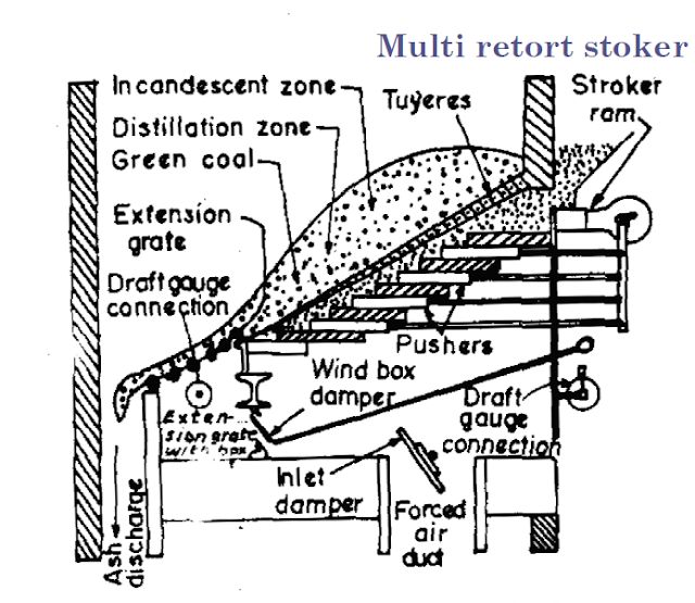
- The underfeed stokers fall into two main groups, the single retort and multiple retort stokers

- The fuel is placed in large hopper on the front of the furnace, and then it is further fed by reciprocating ram or screw conveyor into the bottom of the horizontal trough.
- The air is supplied through the tuyeres provided along the upper edge of the grate.
- The ash and clinkers are collected on the ash plate provided with dumping arrangement.
- The coal feeding capacity of a single retort stoker varies from 100 to 2000 kg per hour.

- The multi retort stoker consists of alternate retorts for pushing coal and tuyere boxes for supplying air.
- The coal falling from the hopper is push by reciprocating ram during the inward stroke.
- The ash is collected at the another end as shown in figure.
- The amount of coal and air pressure in main wind box is varied to meet the variable load demand.
- The number of retorts may vary from 2 to 20 with capacity from 300 to 2000 kg per hr per retort.
In pulverized fuel firing system, the coal is powdered and then charged into the combustion
chamber with the help of hot air current. The main purpose of pulverizing coal is to increase the
surface area of exposure to the combustion process, which results in faster and efficient
combustion.In burning the pulverized coal, the secondary air required for the complete combustion
of fuel is supplied separately to the combustion chamber. The resulting turbulence in the
combustion chamber helps for uniform mixing of fuel and air. The air required to carry the
pulverized coal and dry it before entering the combustion chamber is termed the Priming Air,
and the air supplied separately for complete combustion is termed the Secondary Air. Pulverized
coal firing systems are universally adopted far large scale power plants.
The choice of pulverized fuel firing system depends upon the size of the boiler unit, type of
coal available, cost of coal, type of load (i.e., fluctuating or constant), the load factor and
availability of trained personnel. Generally such systems are not economical for small capacity
thermal power plants
Advantages of using pulverised coal
1) A wide variety of low grade fuels (coal) can be used and burnt easily.
2) Greater surface area is exposed for combustion and hence combustion is faster and efficient.
3) The system is free from clinker and slagging troubles.
4) Combustion control is easy, and hence the system gives fast response to load changes.
5) Preheated secondary air (up to 350°C) can be used, resulting in rapid flame propagation and
faster heat supply to the boiler.
6) The pulverizing system can be maintained or repaired without affecting the combustion process.
7) It has a very high rate of heat release.
8) Banking losses (un burnt fuel with ash) are lower, as compared to stoker firing.
9) The boilers can be started from cold very rapidly.
10) Usually combustion will be smokeless.
Disadvantages of Pulverised system
1) The capital investment of the system is high as it requires additional equipments (for pulverizing,
and handling).
2) Its operation and maintenance costs are very high.
3) It produces fly-ash/fine dust and needs costly fly-ash removal equipments like electrostatic
precipitators.
4) The chances of explosion are high as coal burns like a gas.
5) The storage of powdered coal requires special attention as it has possibilities of fire hazards.
6)
Skilled workers are required for safe-operation and maintenance.
7) Air pollution takes place by the emission of fine particles of grit and dirt.
8) The removal of liquid slag formed from low fusion temperature ash requires special handling
equipments.
Pulverised Fuel Burning System
There are two common methods of pulverized fuel burning systems
1. Unit system
2. Central or Bin system
1. Unit System
In this system, each burner and a pulveriser constitute a unit. It consists of a raw coal bunker, a feeder, pulverizing mill, separator, and the burner. In operation, the raw coal is supplied to the bunker, where it is crushed to the required sizes, the crushed coal is then fed to the pulverizing mill through the feeder at the required rate, depending upon the combustion requirements. Hot gases are passed through the feeder to dry the coal. The dried coal is pulverised in the mill and it is carried to the burner. An induced draft fan is used at the pulverizer to carry the powdered coal to the burner. A separator is provided to separate the grains of bigger size from the powder and returned to the pulveriser for further crushing.

Advantages
1. It is simple in operation and economical than the central system.
2. Combustion is controlled directly after pulveriser.
3. Maintenance cost is low.
4. Fuel supply to the burner can be controlled easily.
Disadvantages
1) The performance of the pulverizing mill is poor as the system operates at variable loads.
2) The total capacity of mills must be higher than the central system.
3) The unit system of fuel burning is less flexible.
4) Whenever any of the auxiliaries fails the burner has to be put-off.
5) Wear and tear of the fan blades is more since it handles hot air and coal particles.
6) Strict maintenance of pulverizing mill is a must for perfect operation of the system.
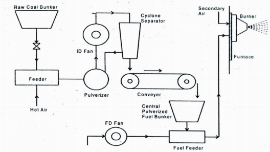
Central or Bin System
Fig. shows schematic arrangement and the principle of operation of a central, or bin system for burning pulverised coal. The crushed raw coal is dried using hot air or flue gases and fed to the pulveriser. The pulverised coal from the pulverizing mill is passed to the cyclone separator where over-sized particles are separated and fed back to the mill.


Pulverised Fuel Burning System
There are two common methods of pulverized fuel burning systems
1. Unit system
2. Central or Bin system
1. Unit System
In this system, each burner and a pulveriser constitute a unit. It consists of a raw coal bunker, a feeder, pulverizing mill, separator, and the burner. In operation, the raw coal is supplied to the bunker, where it is crushed to the required sizes, the crushed coal is then fed to the pulverizing mill through the feeder at the required rate, depending upon the combustion requirements. Hot gases are passed through the feeder to dry the coal. The dried coal is pulverised in the mill and it is carried to the burner. An induced draft fan is used at the pulverizer to carry the powdered coal to the burner. A separator is provided to separate the grains of bigger size from the powder and returned to the pulveriser for further crushing.
Advantages
1. It is simple in operation and economical than the central system.
2. Combustion is controlled directly after pulveriser.
3. Maintenance cost is low.
4. Fuel supply to the burner can be controlled easily.
Disadvantages
1) The performance of the pulverizing mill is poor as the system operates at variable loads.
2) The total capacity of mills must be higher than the central system.
3) The unit system of fuel burning is less flexible.
4) Whenever any of the auxiliaries fails the burner has to be put-off.
5) Wear and tear of the fan blades is more since it handles hot air and coal particles.
6) Strict maintenance of pulverizing mill is a must for perfect operation of the system.
Central or Bin System
Fig. shows schematic arrangement and the principle of operation of a central, or bin system for burning pulverised coal. The crushed raw coal is dried using hot air or flue gases and fed to the pulveriser. The pulverised coal from the pulverizing mill is passed to the cyclone separator where over-sized particles are separated and fed back to the mill.
The pulverised coal is then transferred from the separator to the central bunker (bin)
through a conveyer system. The pressurized air from the forced draft fan, supplies the stored coal
to the burner. This air not only carries the fuel, but also acts as the primary air for the combustion
of the fuel. Secondary air is supplied to the burner separately to assist in the complete combustion.
Advantages of Central system
1) Central system is highly flexible and hence can meet any quick changes in the demand.
2) Burner operation is independent of coal pulverization.
3) The pulverizing mill can be stopped when there is a good stock of pulverised fuel in the bin.
4) The fan wear is less as it handles only natural air.
5) Coal size can be controlled efficiently.
Disadvantages
1) Central system is expensive, and occupies more space.
2) It requires complicated coal handling systems.
3) Power consumption in auxiliaries is high.
4) Chances of fire hazards are more since the pulverised fuel is stored.
5) Operation and maintenance costs are high.
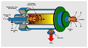
Cyclone Furnace Construction - Working:
- A cyclone furnace consists of a horizontal cylindrical barrel attached through the side of a boiler furnace. The cyclone barrel is constructed with water cooled, tangential oriented, tube construction.
- Inside the cyclone barrel are short, densely spaced, pin studs welded to the outside of the tubes. The studs are coated with a refractory material, usually silica or aluminium based, that allows the cyclone to operate at a high enough temperature to keep the slag in a molten state and allow removal through the tap.
- Crushed coal and a small amount of primary air enter from the front of the cyclone into the burner. In the main cyclone burner, secondary air is introduced tangentially, causing a circulating gas flow pattern.
- The products, flue gas and un-combusted fuel, then leave the burner and pass over the boiler tubes. Tertiary air is then released further downstream to complete combustion of the remaining fuel, greatly reducing NOx formation.
- A layer of molten slag coats the burner and flows through traps at the bottom of the burners, reducing the amount of slag that would otherwise form on the boiler tubes.
- Cyclone Furnaces can handle a wide range of fuels. Low volatile bituminous coals, lignite coal, mineral rich anthracite coal, wood chips, petroleum coke, and old tires can and have all been used in cyclones.
- The crushed coal is fed into the cyclone burner and fired with high rates of heat release. Before the hot gases enter in the boiler furnace the combustion of coal is completed. The crushed coal is fed into cyclone burners .
- The coal is Burned by centrifugal action which is imparted by the primary air which enters tangentially and secondary Air which also enters in the top tangentially at high speed and tertiary air is admitted in the centre.
- Due to Whirling action of coal and air, a large amount of heat is generated (1500-1600°c)and that covered the surface of cyclone and ashes are transformed into molten slag .The molten slag drained from the boiler furnace through a slag tap.
Cyclone furnaces were originally designed to take advantage of four things
- Lower fuel preparation time and costs
- Smaller more compact furnaces
- Less fly ash and convective pass slagging
- Flexibility in fuel types
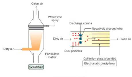
Dust collector is a system used to enhance the quality of air released from industrial and commercial processes by collecting dust and other impurities from air or gas. Designed to handle high-volume dust loads, a dust collector system consists of a blower, dust filter, a filter-cleaning system, and a dust receptacle or dust removal system. It is distinguished from air purifiers, which use disposable filters to remove dust.
Five main types of industrial dust collectors are:
Inertial separators
Fabric filters
Wet scrubbers
Unit collectors
Electrostatic precipitators
Inertial Separators:
Fabric Filters:
Wet Scrubbers:
Electro-static Precipitation:


My wife and i got really thankful Chris could conclude his basic research through the entire ideas he grabbed through your web page. It's not at all simplistic just to be releasing guidelines that many people have been making money from. And we discover we've got you to be grateful to for that. The entire illustrations you made, the simple site menu, the relationships you can aid to engender - it's all excellent, and it's letting our son in addition to the family know that this theme is pleasurable, and that's incredibly serious. Thanks for the whole thing!
ReplyDeleteSteam boiler
Nice blog here! Also your web site loads up fast! What host are you using? Can I get your affiliate link to your host? I wish my web site loaded up as fast as yours lol
ReplyDeleteInstallation Aircondition Vancouver
I precisely needed to appreciate you once more. I am not sure what I could possibly have followed in the absence of the entire aspects documented by you relating to my area of interest. This has been the alarming issue in my position, but being able to see a well-written style you processed it made me to weep with contentment. I am grateful for the information and hope you know what an amazing job you're accomplishing educating people today via your blog post. I know that you have never met any of us.
ReplyDeleteElectric steam boiler
Good Post! Thank you so much for sharing this pretty post, it was so good to read and useful to improve my knowledge as updated one, keep blogging.
ReplyDeletePlant Engineering
It's really a good blog kindly thank you for sharing this.
ReplyDeleteOffshore Engineering Services India
Nice Post! However if you would like to checkout best turbine manufacturers, feel free to contact this one. NCON Turbine in India is one of the leading Power turbine manufacturerswith standard quality. You can check them out or contact their expert turbine engineers.
ReplyDeleteThanks For Sharing Such an informatove post, Good work and great Stuff. Access us to know more about Magnets.
ReplyDeleteMagnetic Separator Manufacturers
Magnetic Drum Manufacturers
Magnetic Head Pulleys for Conveyor Systems Manufacturers
Rectangular Lifting Magnet Manufacturers
Bullet Magnet Manufacturers
Nice blog, Shree Techno Engineers is the top best manufacturer and supplier of Coal Handling Plant and Handling Plant System. We offer bulk powder and granules or particle material for agricultural food, pharmaceutical products, chemicals, coal, and minerals. Which are normally used for long-distance transfer storage and process? https://www.conveyingtechno.in/coal-handling-plant/
ReplyDeleteGenH2 offers Hydrogen supply ranging from 10Nm3/h up to 1000 Nm3/h - Zero carbon emission.
ReplyDeleteFantastic blog! Thanks for sharing a very interesting post, I appreciate to blogger for an amazing post.
ReplyDeletepower plant engineering services
3d scanning reverse engineering services
https://radioaccessory.blogspot.com/2017/03/yankees-joe-girardi-believes-earpieces.html?showComment=1648220333025#c1871483672310759336
ReplyDeletehttps://supply.ctdi.com/shop/productdetail/1500/spare-rrus-32-b2-remote-radio-unit
ReplyDeletehttps://supply.ctdi.com/shop/productdetail/1517103/rus-01-b4
ReplyDeletehttps://supply.ctdi.com/shop/productdetail/171637/service-access-switch
ReplyDeleteLaboratory ovens by AI Furnaces deliver precise temperature control for heating, baking, evaporating, sterilizing, and testing. AI Furnaces offers a range of convection, mechanical and vacuum laboratory ovens with a wide range of capacity, temperature and affordability.
ReplyDeleteAi Furnaces is the premium manufacturer of High-Quality Rotary Furnaces, Tube Furnaces, Controlled Atmosphere furnaces, Muffle Furnaces, Tabletop Furnaces, and CVD & PECVD Furnaces.
ReplyDeletenice article
ReplyDeleteCommitment to safety, quality, and fast turnaround to minimize outage downtime and provide the best performance enhancements for boilers. Power Generation Boilers
ReplyDeleteI was looking for an appropriate clarification for Green Freight. I much appreciate, administrator, for sharing such awesome substance on this theme. Presently I have all I require about it. Here’s another enlightening substance for green transportation program you will get well-informed data about it here.
ReplyDelete